Loading CAD · 0%
scroll
Approach, capture, chilldown and fill from the recorded ROS 2 run, plus the fault cases. The two vehicles are NASA public-domain stand-ins; the module and coupling are our CAD, enlarged 8 times so they can be seen.
Earth: NASA Blue Marble (2004 day / 2002 clouds and lights), Reto Stöckli & Robert Simmon. Day source · Cloud source · Night source · public domain US government imagery (NASA usage guidelines). Historical composites, not live weather. Close-range detail: Blue Marble NG January 2004, 21600 × 10800, cropped to 0–50° N, 115–41° W (about 1.85 km per pixel). Stars: Yale Bright Star Catalogue, 5th revised edition (9,096 stars to magnitude 6.5, J2000), placed for 13 Nov 2026 00:00 UTC; size and colour from magnitude and B−V.
Spacecraft models: NASA 3D Resources · public domain. SSL-1300 and Landsat 8 are illustrative host/client stand-ins. Recorded plant: LOX only.
Spacecraft: NASA 3D Resources, public domain; SSL-1300 and Landsat 8 are stand-in vehicles, not CryoLink flight configurations. Module and coupling: project CAD. Tanks and connecting plumbing are explanatory cutaways, with enlarged line diameters and particles for visibility. Liquid geometry is a volume-correct spherical segment with a decorative meniscus, not a free-surface CFD result. Recorded fill sets receiver volume; recorded supply mass sets tanker inventory, including vent losses. The internal tank volumes follow the plant: supply 2000/1141 + 0.5 = 2.253 m³ (2000 kg load and 0.5 m³ ullage ASSUMPTIONS), receiver 0.922 m³ (1000 kg at about 95%). At 1141 kg/m³, equivalent spherical diameters are 1.63 m and 1.21 m. A common 0.5 display units/m scale is used for vehicles and tanks. Host overall span 26 m and client overall extent 12 m are ASSUMPTIONS; USGS gives Landsat 8’s 3 m bus and 9 m solar array. The generic SSL-1300 asset has no verified configuration-specific overall dimension. CAD hardware is enlarged 8× for readability; coupling B moves with the client into A. Lines run within each vehicle, with no free hose. Tank camera makes vehicle skins translucent to expose the internal inventory.
Approach: unforced Clohessy–Wiltshire relative motion, NASA relative-motion reference; μ = 3.986004418 × 10¹⁴ m³/s², Earth radius 6371 km, circular altitude 400 km. Illustrative initial conditions are solved backward from a 0.005 m/s closing velocity at the capture boundary, with a 120 s approach. Range is enlarged for composition. MuJoCo then supplies gap, lateral deflection and tilt. CAD hooks interpolate to 22° open; switch bits determine closure. Poppet timing is illustrative and follows inlet bits. Latching is illustrated as a 3 s stroke. Playback caps approach at 18× and contact capture at 1×; the speed control applies to subsequent recorded operations.
Oxygen saturation and density: project lox_table.py, generated with CoolProp 8.0.0. Velocity = recorded mass flow / (90 K liquid density × CAD 22 mm bore area). Plant hydraulics retain their original 16 mm assumption. Bubbles indicate wall or outlet above total-line-pressure saturation; this is a thermal cue, not recorded vapor fraction. Frost is a temperature-colored illustrative wall coating, not atmospheric frost in vacuum. Methane has no plant data. Stars, vents and vehicle mounting are display assumptions. Earth uses NASA Blue Marble imagery; lighting and atmosphere are illustrative. ROS pulses use documented node rates (1 or 10 Hz); sensor stream is capped at 10 Hz simulation time in these accelerated recordings. Chilldown snapshots miss brief inlet pulses: the recorded mass-flow samples are zero while the wall cools and supply inventory falls. Thermal bubbles remain visible without forward advection at those samples. No live ROS connection.
Each tile states the requirement, the method and the result. Numbers are labeled: measured (a cited test), computed (our analysis) or assumption (a design input).
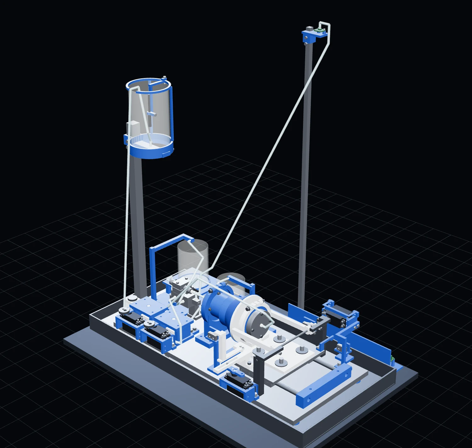
The bench version of the coupling mates, latches, conditions the line, fills, drains and demates on its own. Water stands in for liquid oxygen, and chilled water stands in for chilldown. The flight software drives it unchanged through a small safety controller.
T1–T8: proposed acceptance targets, not achieved hardware results. Source: prototype test procedures.
| Test | Pass limit | Compared with |
|---|---|---|
| T1 · Dry mate | ≥90% capture per condition | MuJoCo: 60 of 60 captured (to 7 mm, 1°) |
| T2 · Interlocks | every unsafe feed-open rejected | ROS 2 latch fault |
| T3 · Disconnected hold | ≤1 mL/min per half | no seal-leakage simulation |
| T4 · Mated leak check | ≤1 mL/min; pressure limit from measured noise | leak-check mode sequence |
| T5 · Conditioning | wall below 15 °C for 5 s; no receiver gain | water-rig lumped prediction; LOX sequence only |
| T6 · Autonomous cycle | no hand help; demate spill ≤5 mL | nominal replay timeline |
| T7 · Link loss | feed closed, drain open within 2 s | watchdog replay: feed closed at 1.70 s; power loss needs manual clamp |
| T8 · Endurance | ≥18 of 20 cycles | repeat T6; no endurance simulation |
COMPUTED · water-rig lumped model. Gate time includes the probe hold. Low/base/high vary flow, heat transfer and probe lag; these are scenarios, not confidence limits.
COMPUTED water used: 129 / 143 / 176 mL. ASSUMPTIONS: source 2 °C, initial 22 °C, probe lag 8–40 s and spool contact 2 W/K. The coupling remains warmer than the probe. Source: T5 conditioning model and saved JSON.
computed $313.94 vendor carts from MEASURED list prices. Before tax, shipping, local hardware and lab fees. Source: order list, 6 Nov 2026.
Each cryogenic transfer program today builds hardware for its own vehicle; we found no one selling a complete cryogenic transfer module to other vehicle builders. Coupler suppliers and depot developers work nearby, so integration and flight evidence must earn our place.
It could. No patent or physics stops it, and SpaceX already used the same public NASA research.20 The answer is about who buys.
Risks we track: NASA says Blue Origin will defer propellant transfer for its 2028 landing,25 and the coated, pulsed chilldown we use is in a pending NASA patent, so we need a license or a different design.26
Ground units first, then qualified flight modules and a separate retained-module service. Depot ownership needs its own financing. The base model below uses uncontracted demand and labelled cost assumptions. NASA's 2020 Tipping Point awards to four cryogenic demos total $256.1M (MEASURED).
Sold to tanker, depot and lander builders. Water rig first, then liquid nitrogen, then LOX at a qualified site.
Our own vehicles carrying the module.
Propellant sold where missions need it.
Peak unfinanced cash deficit plus liquidity buffer.
Assumed raises, conditional on technical and customer evidence.
Trailing revenue and operating cash flow must both pass the model goal.
Model revenue, not booked sales.
Model revenue, not booked sales.
Model revenue, not booked sales.
Source: Part I model_out.json, years and summary. Prices, adoption, qualification timing and financing are assumptions. No depot revenue is included. Capital need and planned equity are different quantities.
Tell us your vehicle, the propellant (liquid oxygen or methane), how much you need to move and when. We start with a fit check for your interface.
Ask for our simulation results, the water-rig test plan, or a joint test. We share data as the tests run.
CryoLink is at the concept stage: the module is in design, and hardware testing starts with the water rig.


